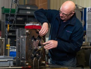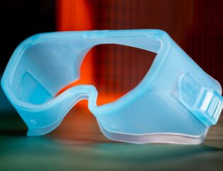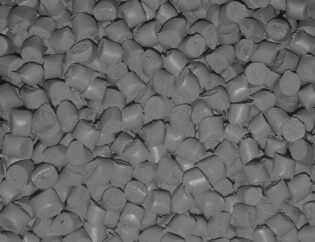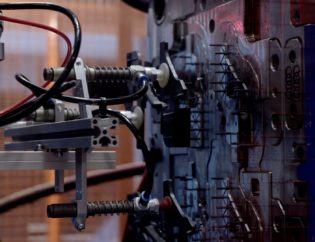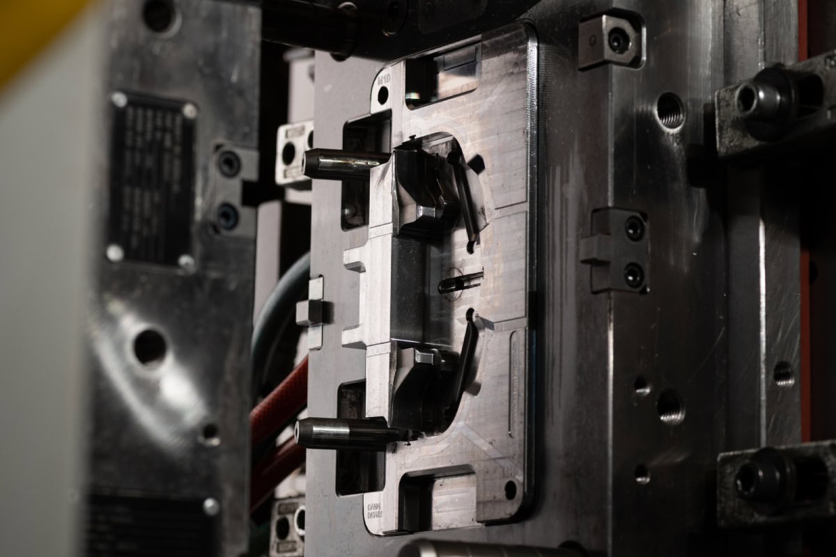
The quality of your plastic components are reliant on three vital elements: the polymer used in the injection process, the injection machines themselves, and the tooling that the polymer is injected into to form the final part. All three stages play an important role in the moulding process, however, the moulding tool can be a costly and time-consuming problem if some of the below elements aren’t considered.
At MGS, we understand that it’s exciting launching a new product, there’s often years of research and development that has gone into the final design. However, it’s crucial that you think about the “moldability” of your part. Especially with your design considerations, such as:
- Material
- Nominal wall thickness
- Ribs
- Undercuts
- Coring
- Bosses
- Radii
- Texture
- Recesses
- Draft Angles
Once you’ve reviewed your part, it’s time to think about the mould tool itself. There are several factors that contribute to the cost of the tooling, including:
Number of Cavities
Multi-cavity tooling contains more than one cavity of the same part. A family mould also contains multiple cavities; the parts are usually a similar size but have a different design.
Tool Material
This can vary depending on the polymer, P20 Steel is often used for materials such as ABS, PP, HDPE, LDPE. Whilst you might have H13 for more aggressive polymers. Stainless Steel is another example of tool material that can be used.
Feed Systems
This can be either a hot runner system or a cold runner system. A hot runner keeps the material in a molten state throughout the duration of the runner process until it flows into the mould cavity. In a cold runner system, the runners and the mould are maintained at the same temperature. There are different variations of both runner systems that can be used for tool design.
Part Size
The size of the part or multiple parts will Impact mould size, which in turn determines the cost and the machines it can be used with. As well as the unit price.
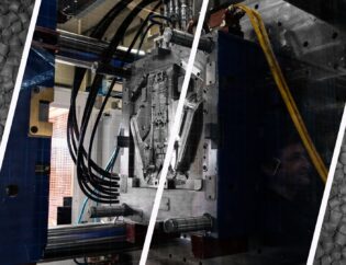
Upon completion the tool is placed inside an injection moulding machine, the moulds consist of both moving and fixed platens which are clamped together at the beginning of the injection mould cycle. Molten polymer is then fed into the clamped mould at a very high pressure, the screw moves forward rapidly pushing the molten plastic from the barrel through the nozzle into the mould.
We have more information about the plastic injection moulding process in this insight post.
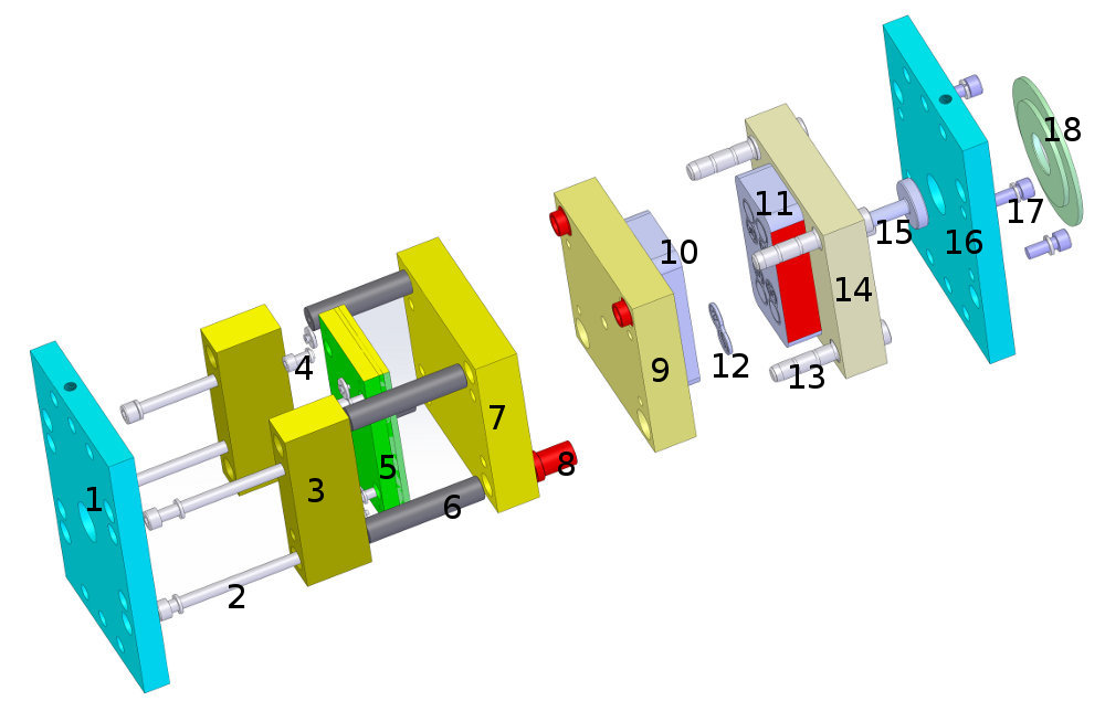
(Credit Toolcraft)
- Moving half back plate
- Bolts
- Risers
- Ejector plate feet
- Ejector locating plate & ejector plate retainer
- Bolster sleeves
- Moving hald support plates
- Guide bush
- Core retaining plate
- Mould core
- Mould cavity
- Moulded part
- Guide pins
- Cavity retaining plate
- Sprue bush
- Fixed half back plate
- Bolts
- Location ring
How can we support your project?
Together we can determine the best design, material and production decisions for optimum quality, speed and value.
